Safety
Product description
Scope of delivery
Specification
Installation
Flushing and venting
Electrical connection
Operating Panel
Delivered condition
Setting the control mode
Setting the actual time
Setting operating times
Resetting to factory settings
Service and replacement
Faults and remedies
Limited consumer warranty
Disposal
Contact
These instructions apply to all specified product series and describe safe and appropriate use at all stages of operation.
Warnings and symbols
General safety information
- Installation, electrical connection and commissioning of the pump may be carried out only by qualified contractors and all general and local safety measures must be observed.
- Operating instructions and associated documents must be complete, legible and accessible at all times.
- Before carrying out work on the pump, read and ensure that you understand the operating instructions.
- This circulation pump is suitable only for water of potable quality.
- The pump should be operated only if it is in technically perfect condition. It must be used only in accordance with intended use, with an awareness of safety and risks, and in accordance with these instructions.
- Before any installation and maintenance work, disconnect the motor from the power supply and secure against reconnection.
- The use, cleaning and maintenance of this device by children aged 8 years or older, persons of restricted physical, sensory or mental capabilities, or persons with limited experience or knowledge is permitted only if they are supervised or instructed in the safe use of the device and understand the associated risks. Children must not be allowed to play with the device.
COMFORT pumps are efficient circulators designed for hot water recirculation in residential buildings.
These pumps feature a compact design housing and high-performance permanent magnet with an integrated control unit. The spherical rotor, equipped with an impeller, ensures optimal functionality, supported by a robust single-bearing ball system. The pump housing, crafted from drinking water approved brass, guarantees both safety and reliability.
Equipped with built-in temperature sensor, the COMFORT pumps provide precision in maintaining water temperature.
Installation is easy with included cable for electrical connection.
The user-friendly interface, made with LEDs and pushbuttons on the front, offers an intuitive platform to display and set operating times and control modes, ensuring a comfortable and energy-efficient experience for residential use.
Operation and Control modes
- The pump operates based on set operating times and temperature mode, with operating times taking priority. This means that the temperature mode can only be active during the specified operating times.
- LED indicators display the actual time (yellow), operating times (green), with the smallest time segment being 30 minutes.
- In the event of a power outage (such as a power cut or blackout), the pump will always retain selected operating periods. The current time setting is maintained for up to 8 hours. Once power is restored within this period, there is no need for the user to reset the time. Note: Units manufactured prior to production code PC 2523 do not include a power reserve for maintaining current time.
- When the temperature mode is enabled (indicated by a green temperature symbol LED), the pump measures water temperature during selected operating times. It automatically adjusts ON/OFF temperatures based on the maximum temperature measured in the system. For instance, if the maximum water temperature is measured at 113 °F (45 °C), the pump switches OFF at temperatures above 106 °F (41 °C) and turns back ON when the water cools down to below 100 °F (38 °C). The system's maximum temperature is measured every 12 hours during the first 15 minutes, allowing dynamic adjustment of ON/OFF temperatures.
For more details click on this link:
- Pump (integrated check valve, shut-off valve and line cord)
- Insulating shell for pump housing
- Installation and operating instructions
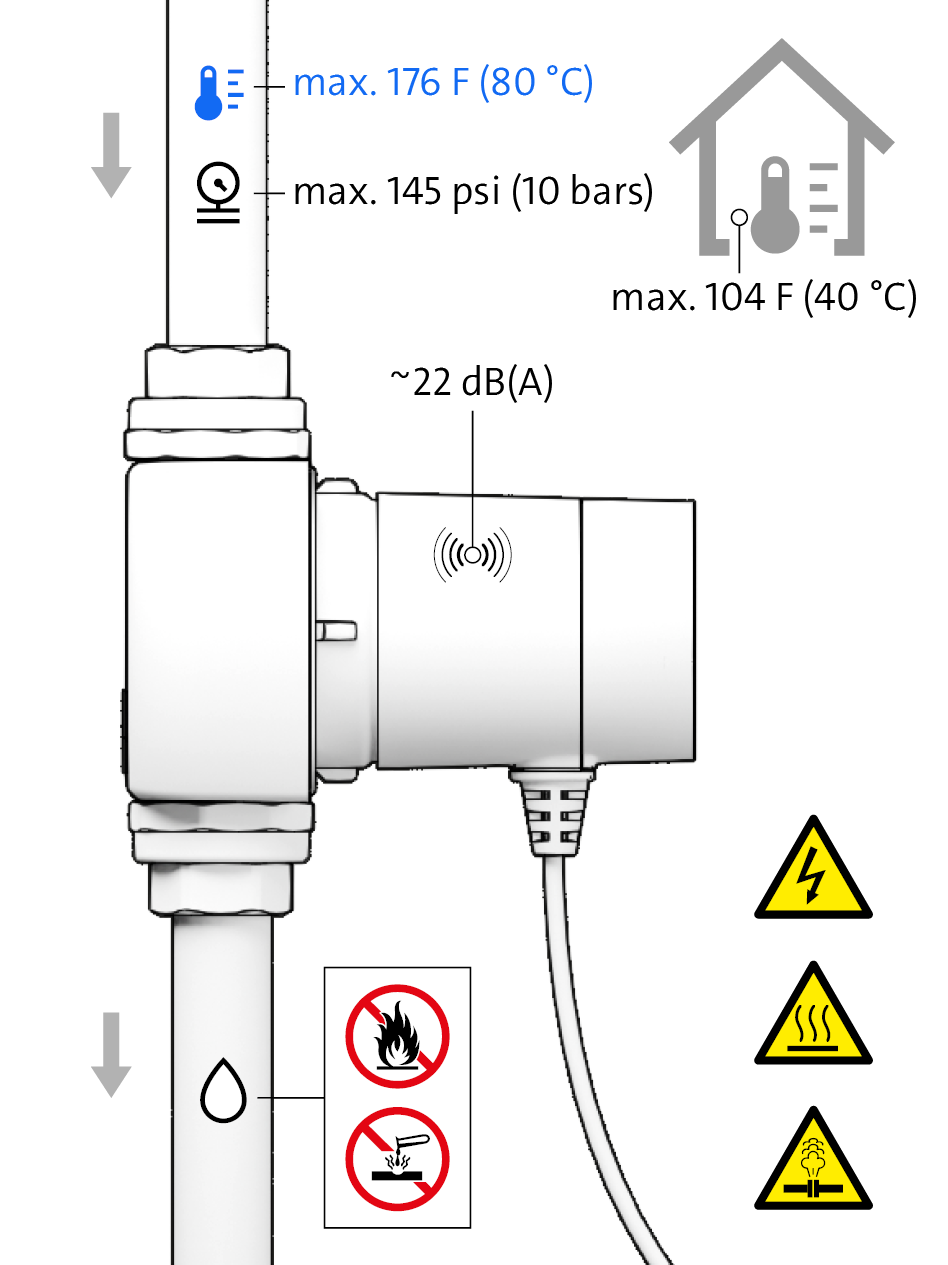
Max. flow rate
2.2 gpm (0.5 m3/h)
Max. head
3.4 ft (1 m)
Supply voltage
1 x 115-230 V / 50-60 Hz
Power consumption
5-7 W
Liquid temperature
36-176 °F (2-80 °C)
Enclosure Class
Type 2
Appliance Class
Double insulated
Pump housing material
Ecobrass (Lead content < 0.2 %)
Permissible water hardness
Unrestricted
Dry-running protection
Yes

CAUTION! Ingress of water will cause physical damage!
- Ensure that the cable entry and cable face downwards after installation.
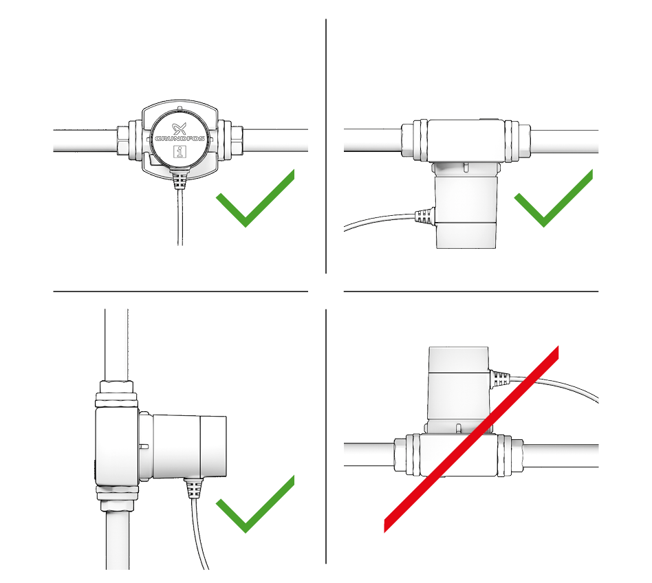
Select a suitable installation site and permissible installation position.
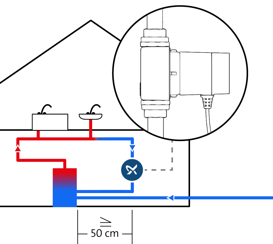
Avoid exposing pumps with temperature mode, such as the T, TDT and TA, to heat:
– Maintain a clearance of at least 50 cm from the DHW heater.
– If the return line opens vertically into the cylinder, install the pump well away from the cylinder entry.
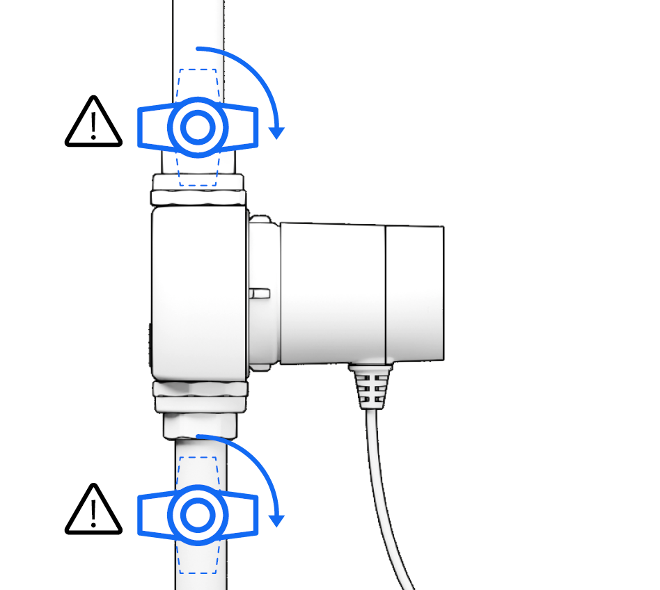
Fit external shut-off (isolating) valves if you need to be able to remove complete pump without draining the system. Integrated shut-off (isolating) valve in pump housing is enough for motor replacement.
- If you are using additional non return or check valve, ensure that is installed in the direction of flow and that has low opening (cracking) pressure of max 0.3 PSI (0.2 kPa or 20 mbar).
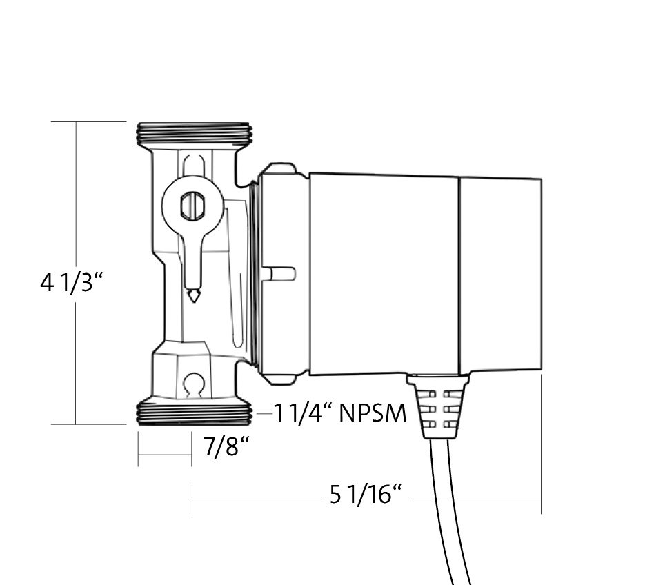
Shut off valve and check valve integrated. Check port to port length, connection type and other dimensions.
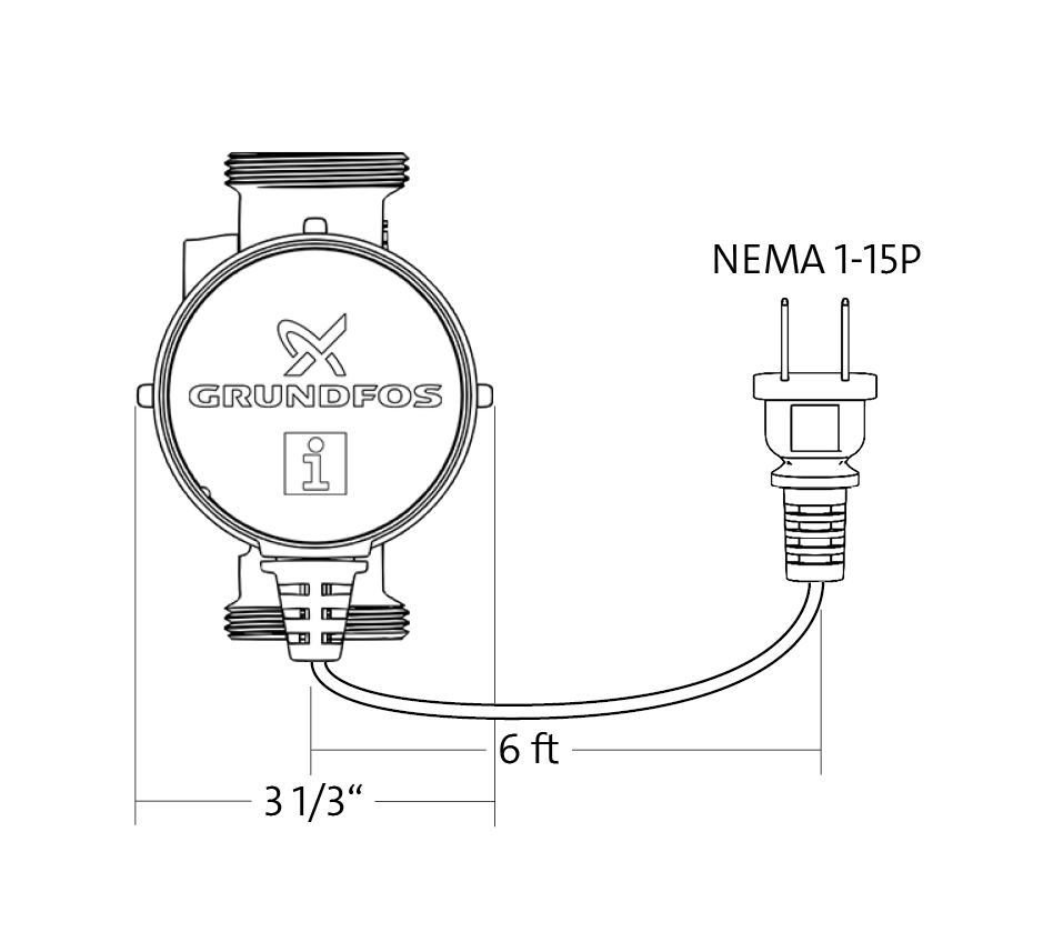
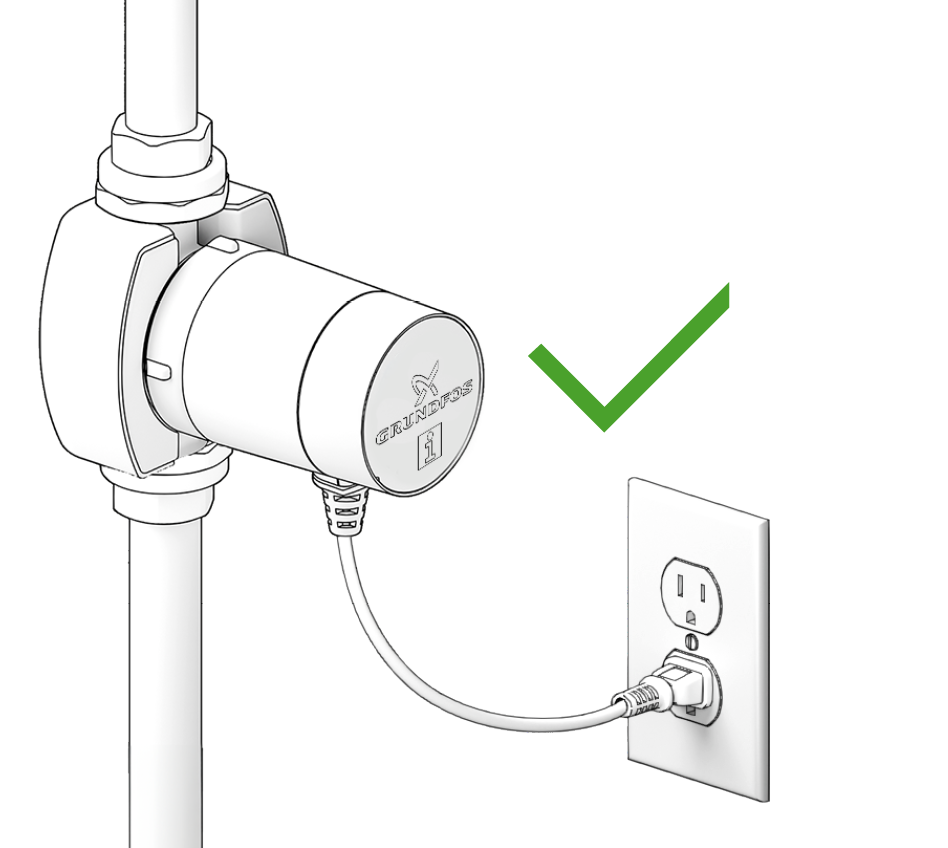
Line cord included.
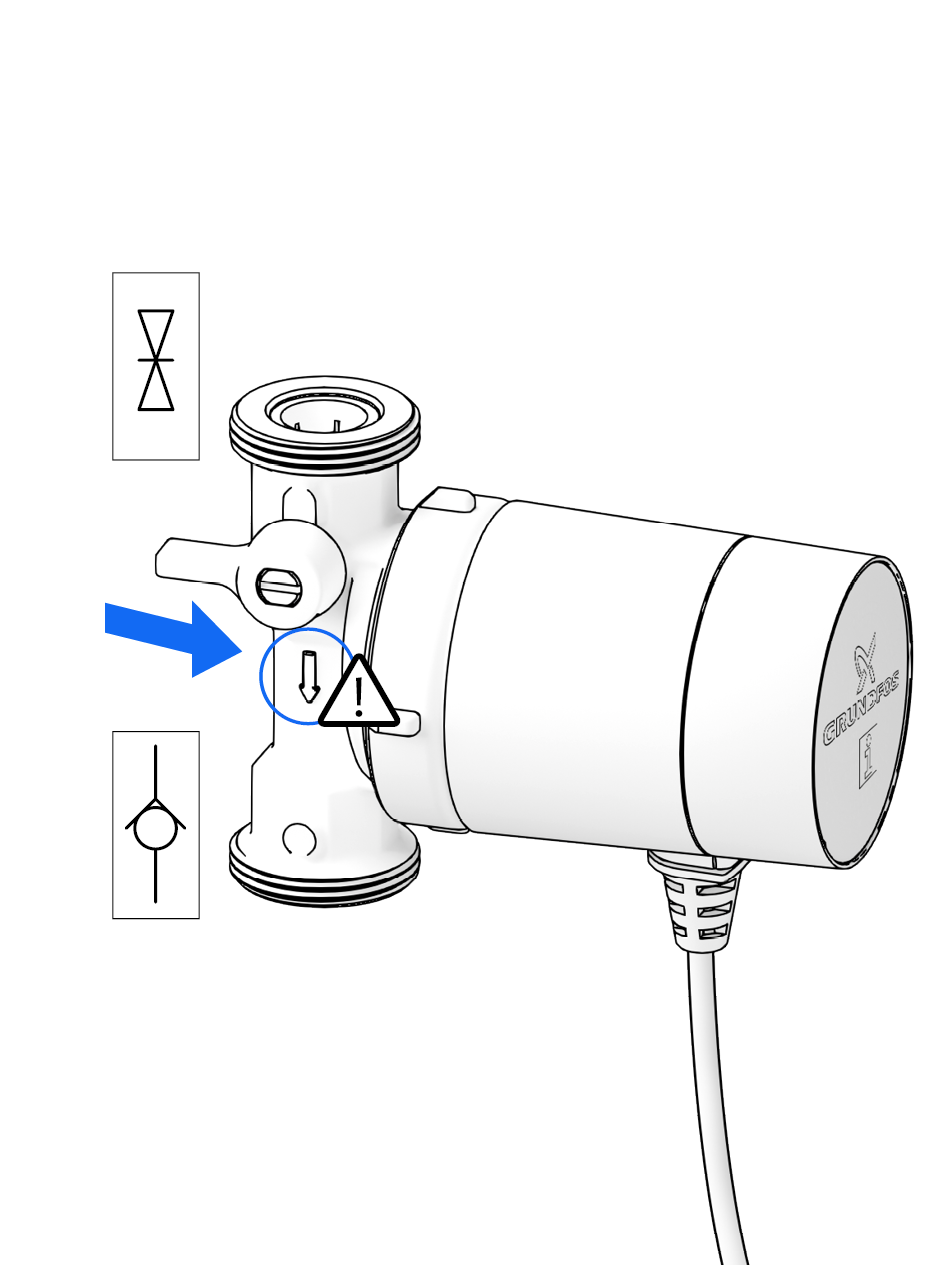
Observe correct direction of flow.
DANGER! Pressurised system!
- Before working on the motor or pump connections, close the shut-off valves.
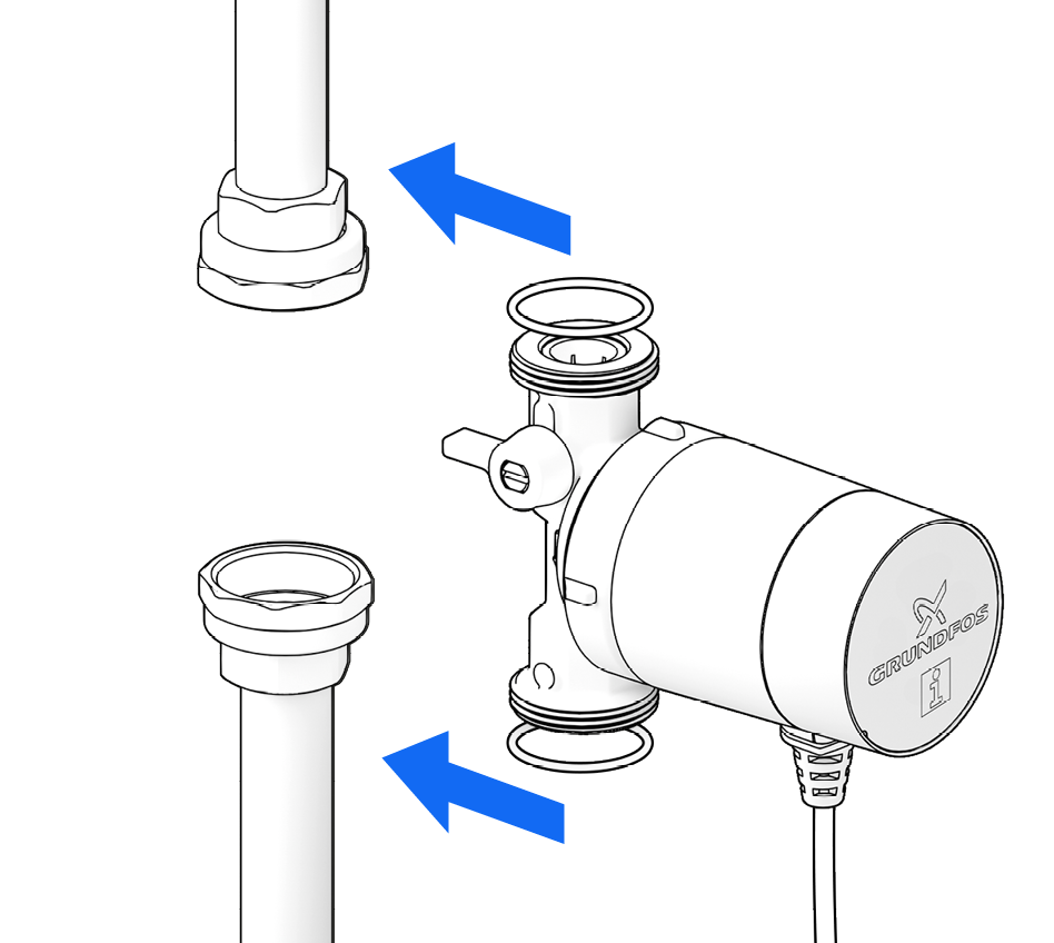
When installing the pump, ensure that it is not under strain.
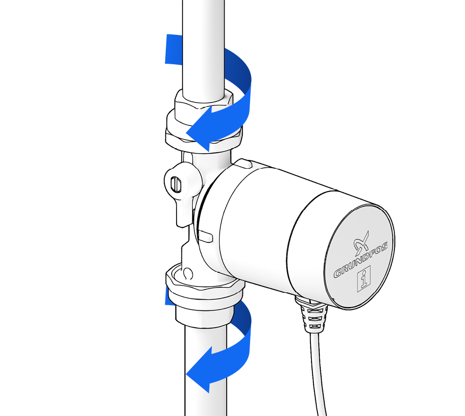
Tighten the fittings.
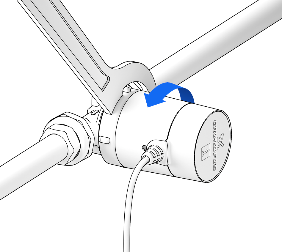
Rotate the pump control panel if necessary so that it is visible (cable exit underneath). To do so, slightly loosen the union nut …
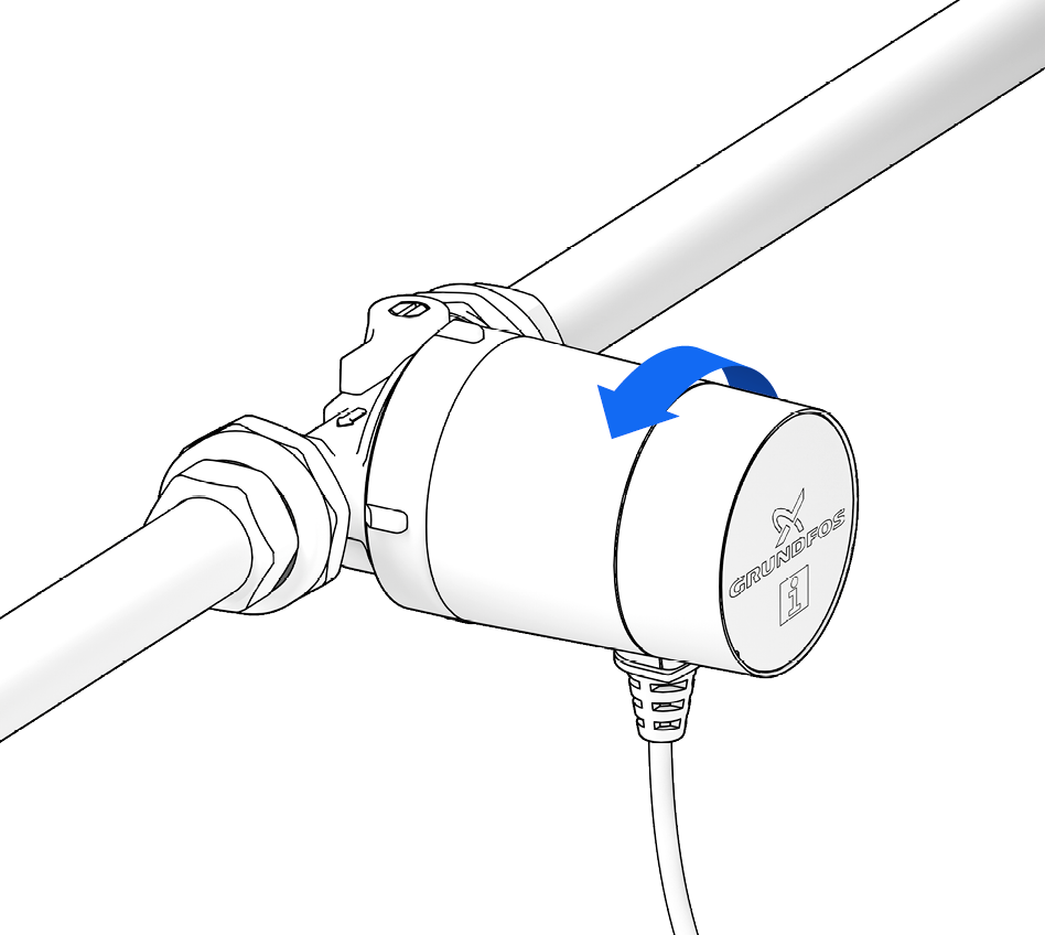
… turn the motor …
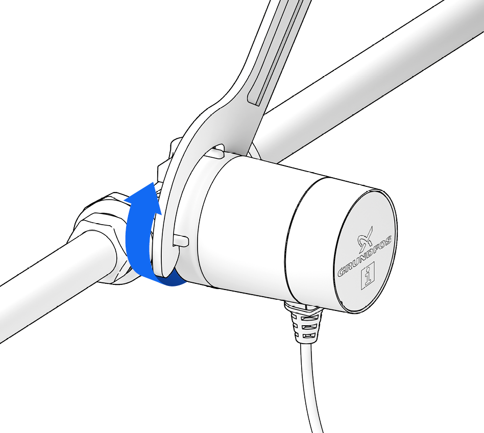
… and retighten the union nut
(max. 20 Nm).
- Fully separating the motor from the pump housing is only necessary for maintenance purposes (see chapters ‘Flushing and Venting’ and ‘Service and Replacement’).
- The pump has dry-running protection. If it runs largely in air, the PCB will repeatedly stop it to protect the rotor bearings. In a fully vented circulation circuit, the pump will run uninterrupted.
CAUTION! Dry-running will damage the bearings!
- Flush the pipework thoroughly with water and vent it.
DANGER! Pressurised system!
- Before working on the motor or pump connections, close the shut-off valves.
WARNING! Risk of scalding due to hot water!
- Avoid direct contact with escaping hot water.
- The pump housing can similarly reach a high temperature due to the hot medium being pumped.
- If no venting valve (fill & drain valve) is present, the system must be vented through the pump housing.
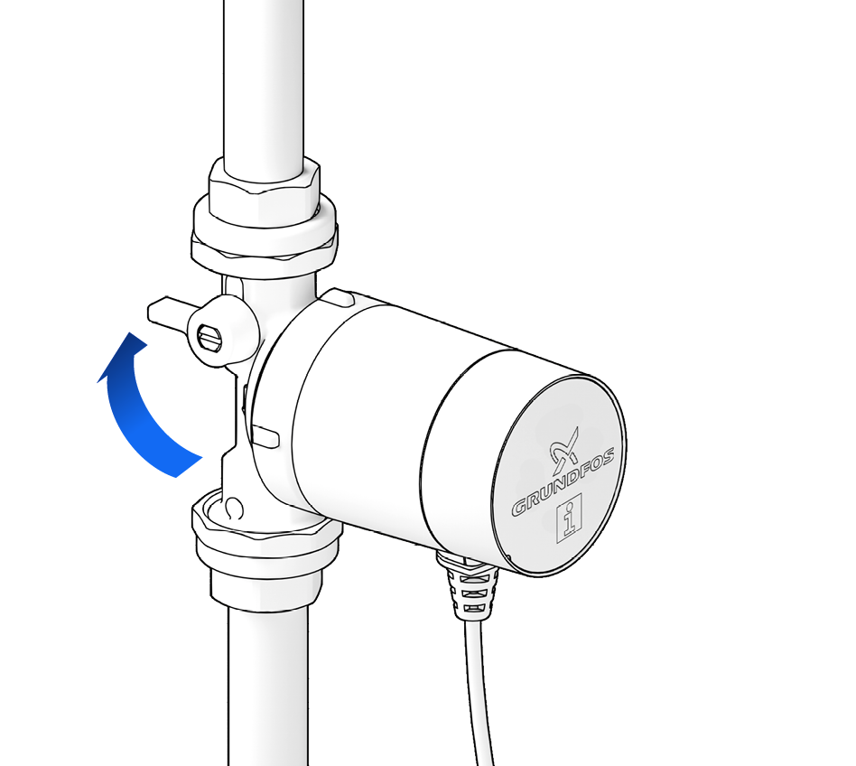
To vent, first close the shut-off valves.
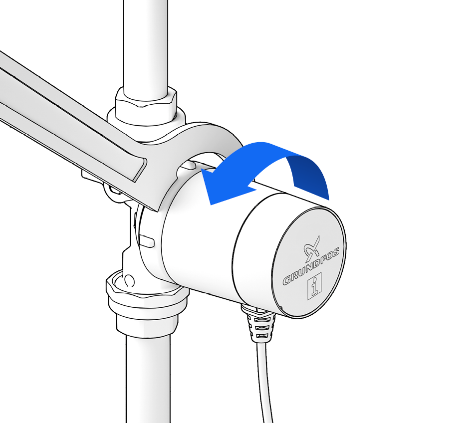
Unscrew the motor from the pump housing …
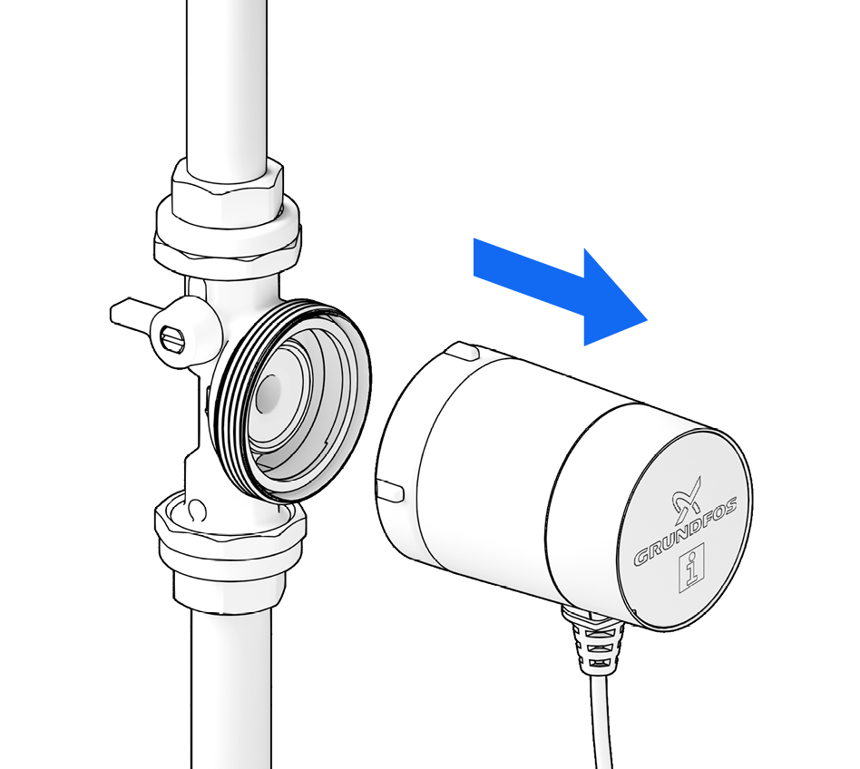
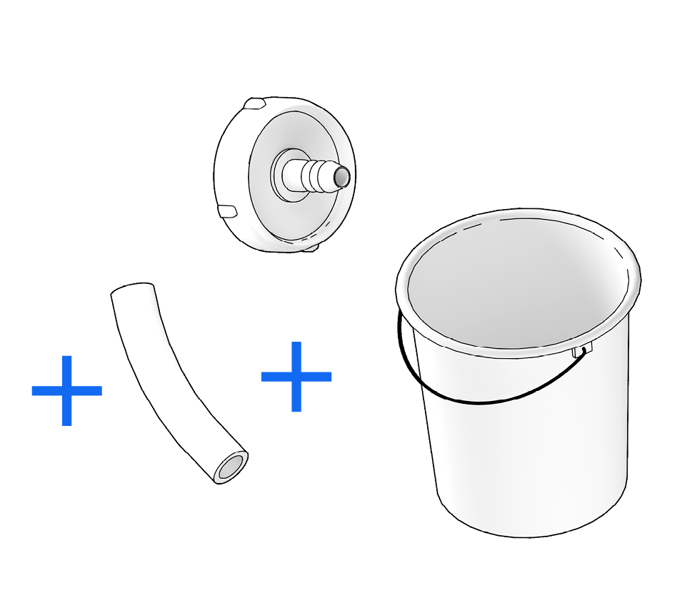
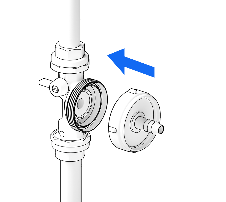
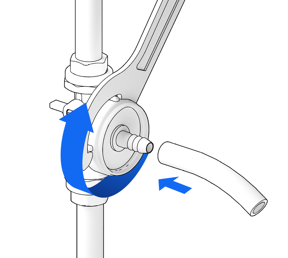
… and screw the venting flange onto the motor (max. 20 Nm).
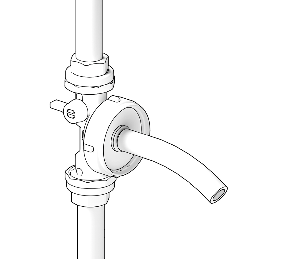
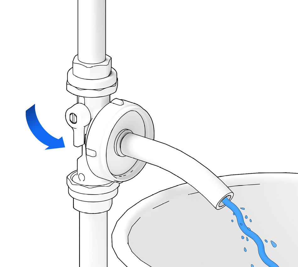
Open the shut-off valve upstream of the pump again and allow water to escape through the venting flange until the pipework is free of air.
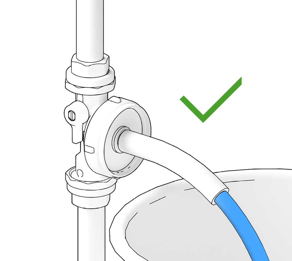
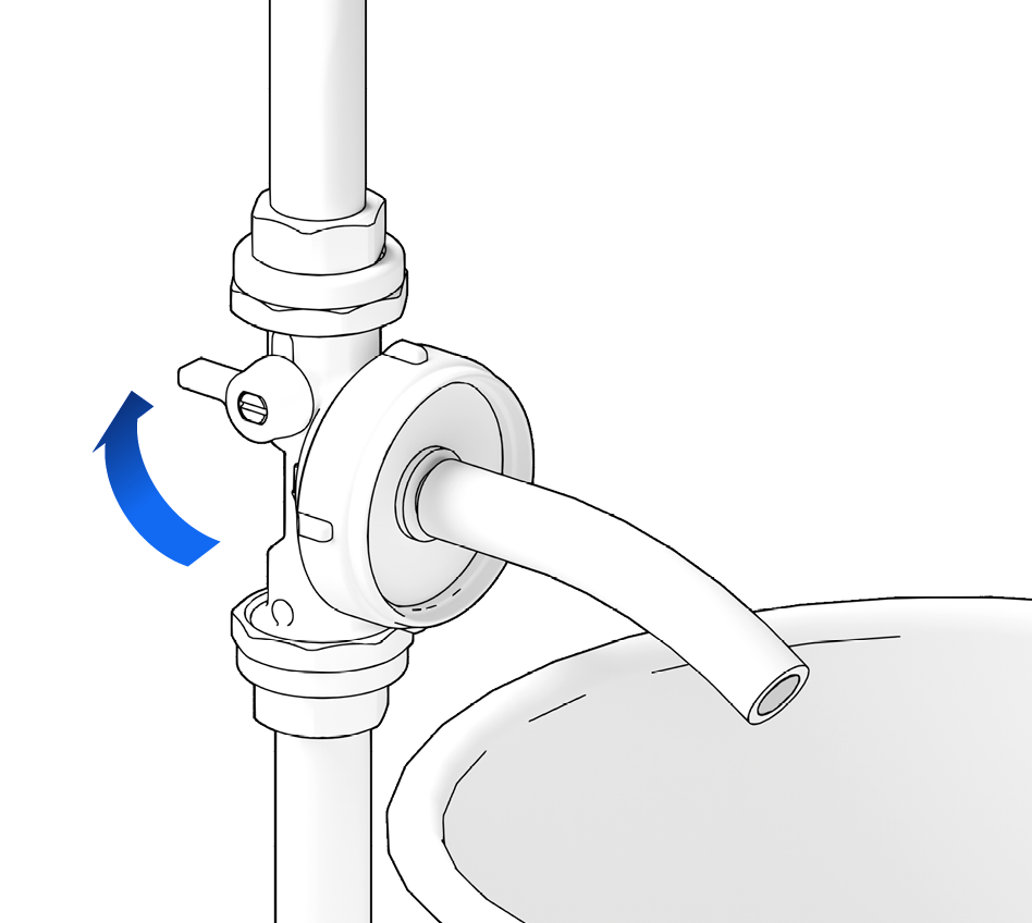
Close the shut-off valve upstream of the pump …
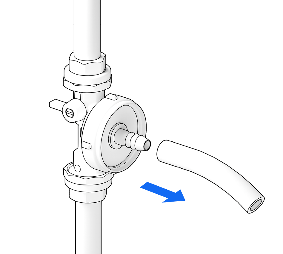
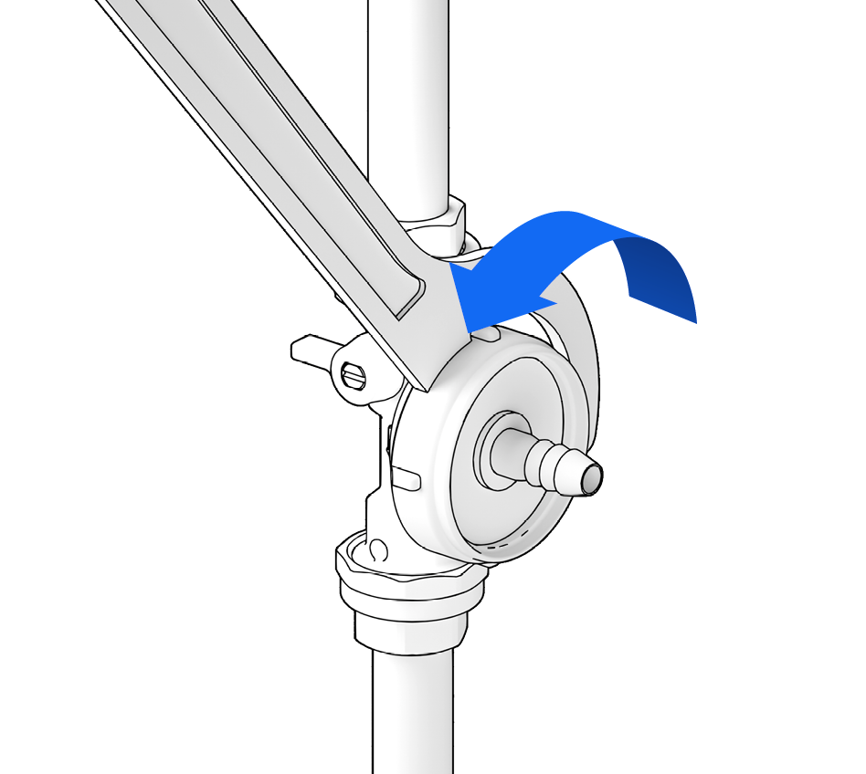
… unscrew the venting flange from the pump …
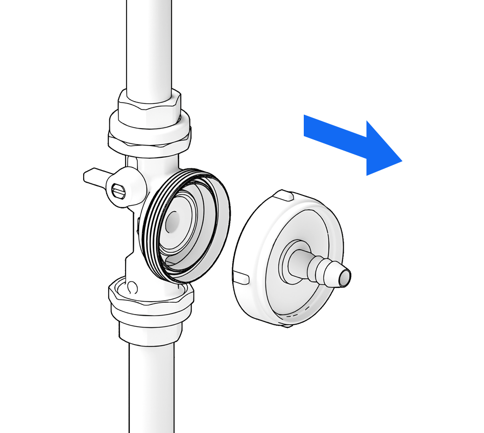
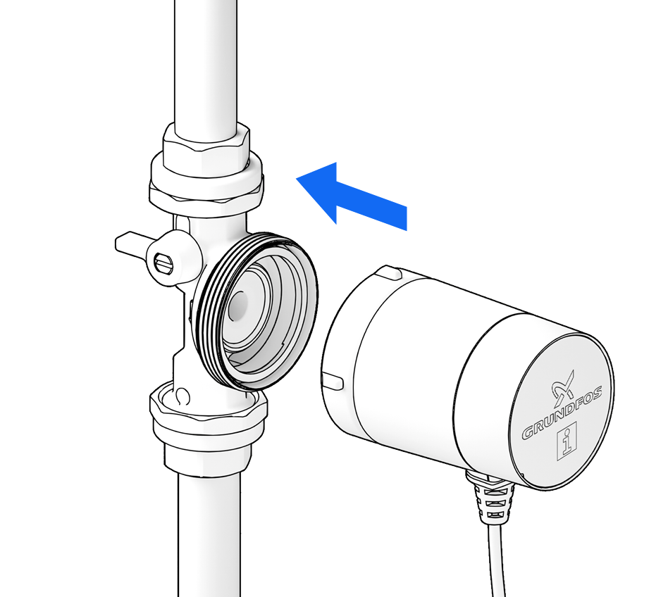
… and reattach the motor to the pump housing.
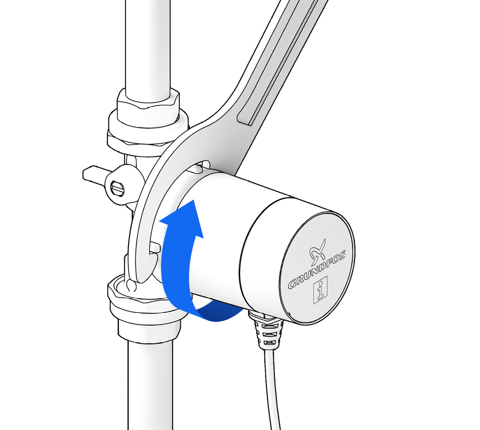
Retighten the union nut
(max. 20 Nm).
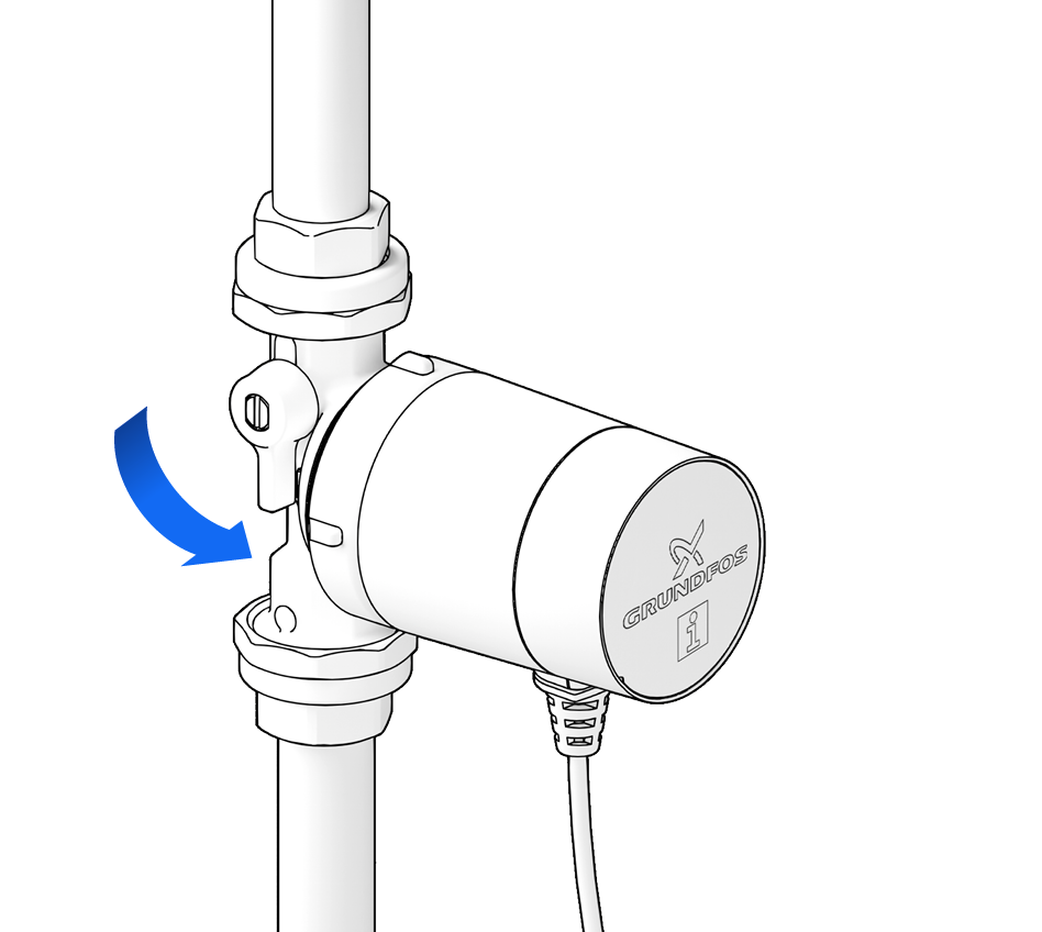
Slowly open the shut-off valves again.
- The pump is driven by a DC motor.
- The transformer for AC operation is built into the motor cap.
- Line cord is integrated in the pump.
DANGER! Electric shock can kill!
- Work on the electrics must be carried out only by authorised contractors.
- Disconnect the pump from the power supply and secure against reconnection.
- Check that no voltage is present.
WARNING! Risk of fire due to electrical ignition!
- Ensure that the pump is connected only to the power supply specified on the nameplate.
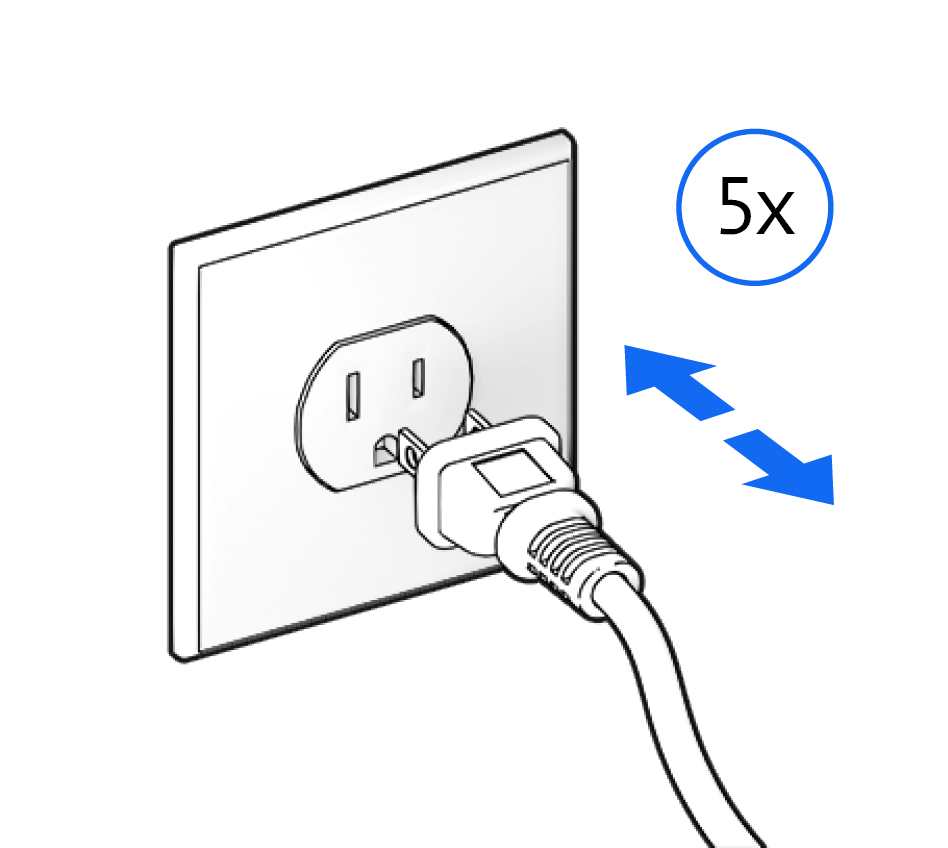
To vent any remaining air, switch the pump on and off several times …
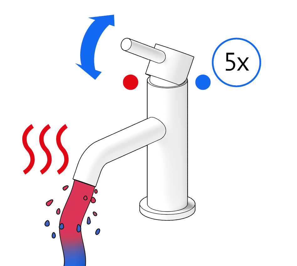
… and open the DHW tap several times …
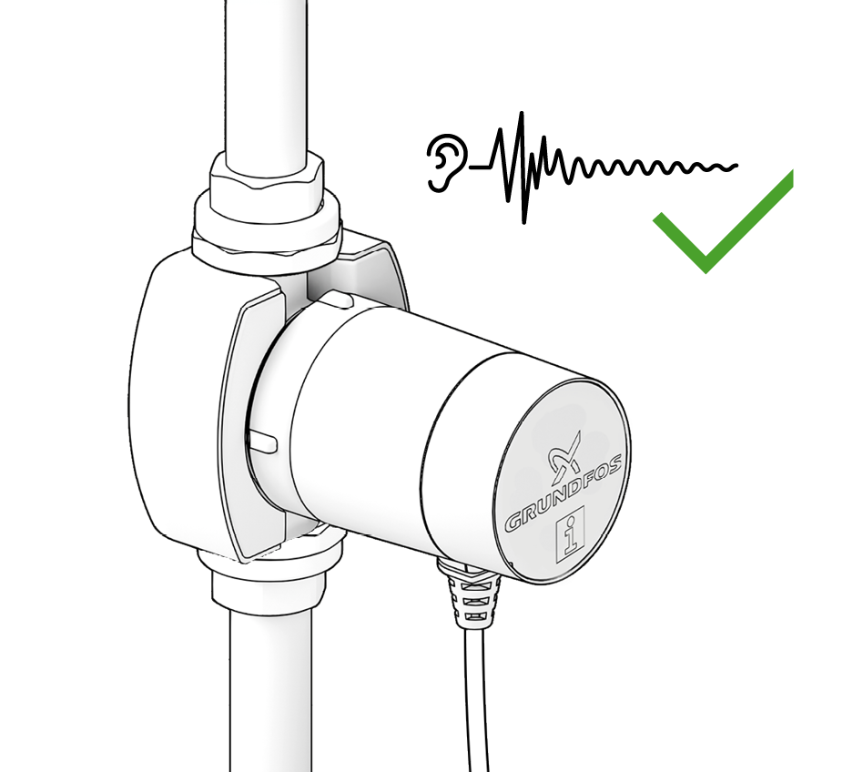
… until the pump runs quietly.


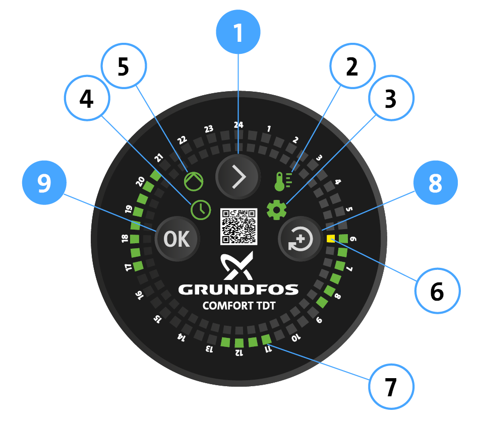
(1) Arrow button
(2) LED Temperature mode
(3) LED Setting mode
(4) LED Timer mode
(5) LED Pump operation
(6) LED Actual time
(7) LED Pump operating times
(8) Change button
(9) OK button

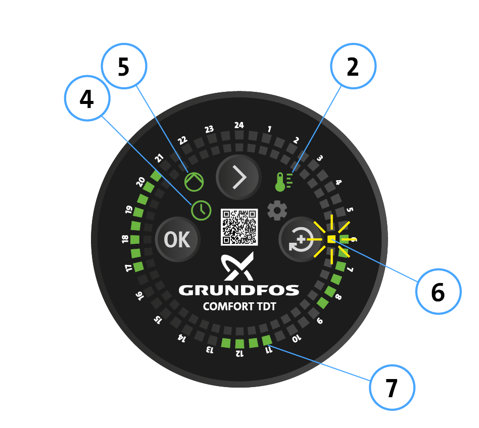
- Pump operates
- LED (4) Timer mode and LED (2) Temperature mode has steady green light.
- Pump operation LED (5) has steady green light.
- The yellow actual time LED (6) flashes at 06:00 AM (time segment 06:00 – 06:30 AM)
- Selected operating times (7) are following: - 06:00 – 09:00 AM
- 11:00 AM – 01:00 PM
- 05:00 – 09:00 PM


- Press Arrow button (1) until requested control mode is selected:
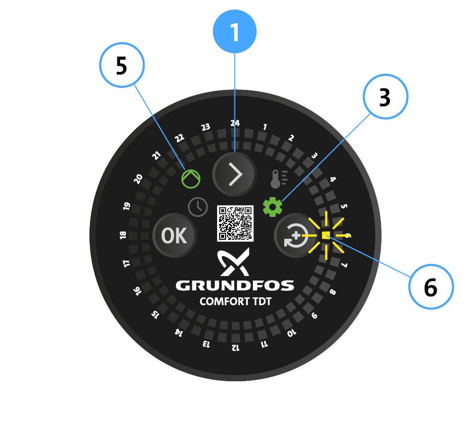
Setting mode: LED (3) and (5) have steady green lights. Actual time (6) has a flashing yellow light.
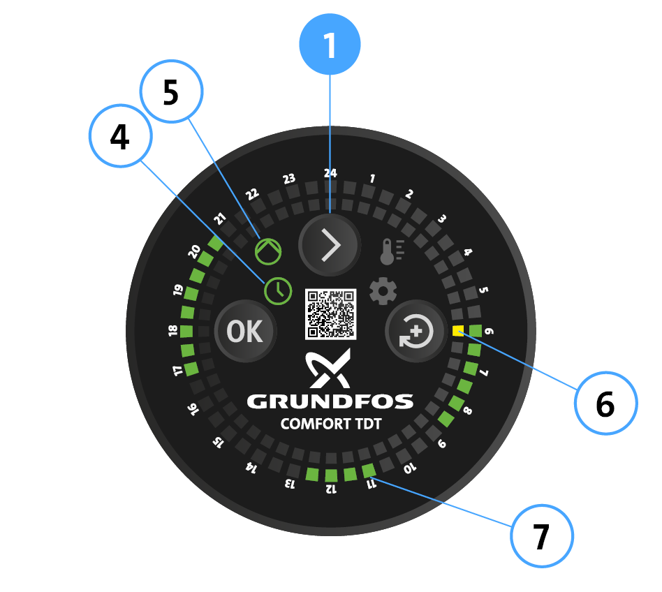
Timer mode: LED (4) and (5) have steady green lights. Actual time (6) has a steady yellow light. Operating times (7) have steady green lights.
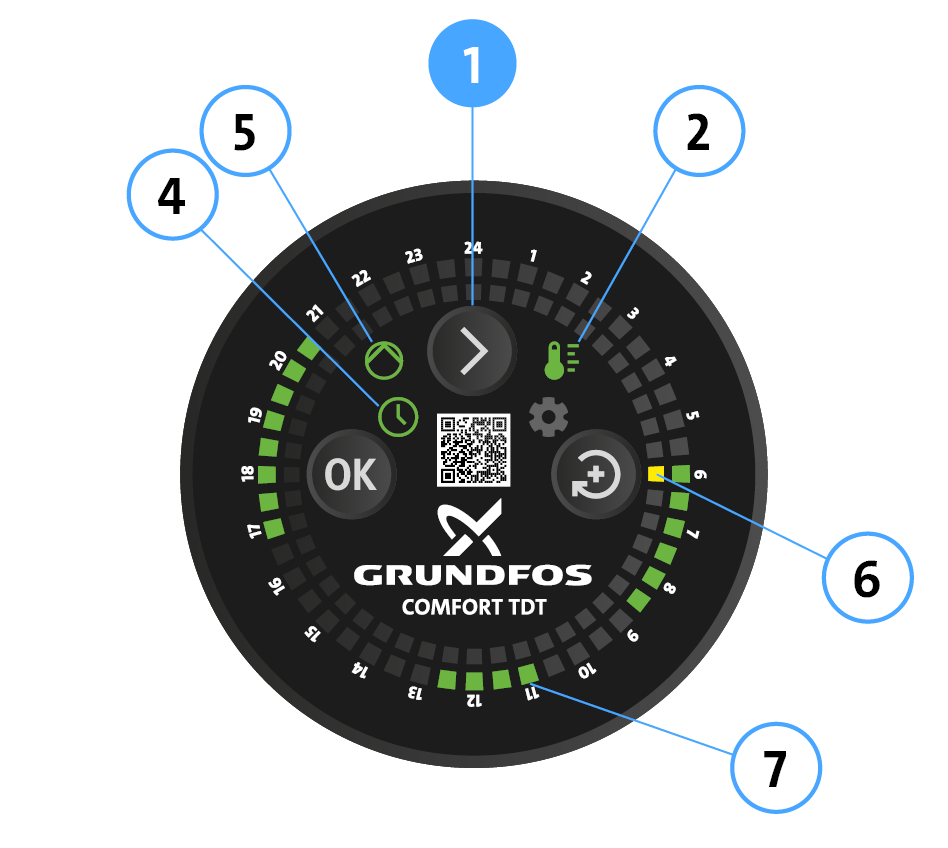
Timer and Temperature mode: LED (2), (4) and (5) have steady green lights. Actual time (6) has a steady yellow light. Operating times (7) have steady green lights.
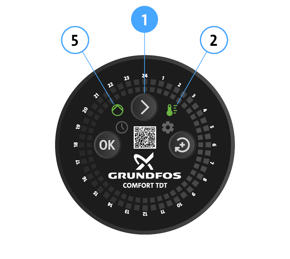
Temperature mode: LED (2) and (5) have steady green lights. Note: This mode is available only on units manufactured with production code PC 2523 and later.


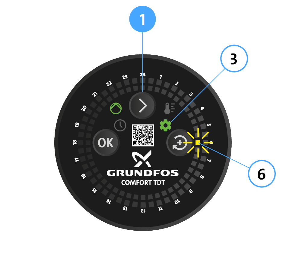
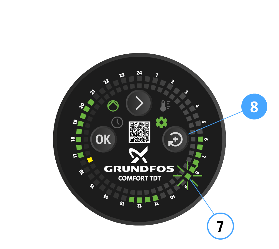
Press Arrow button (1) repeatedly until the setting mode LED (3) has a steady green light. The actual time indicator (6) has a flashing yellow light.
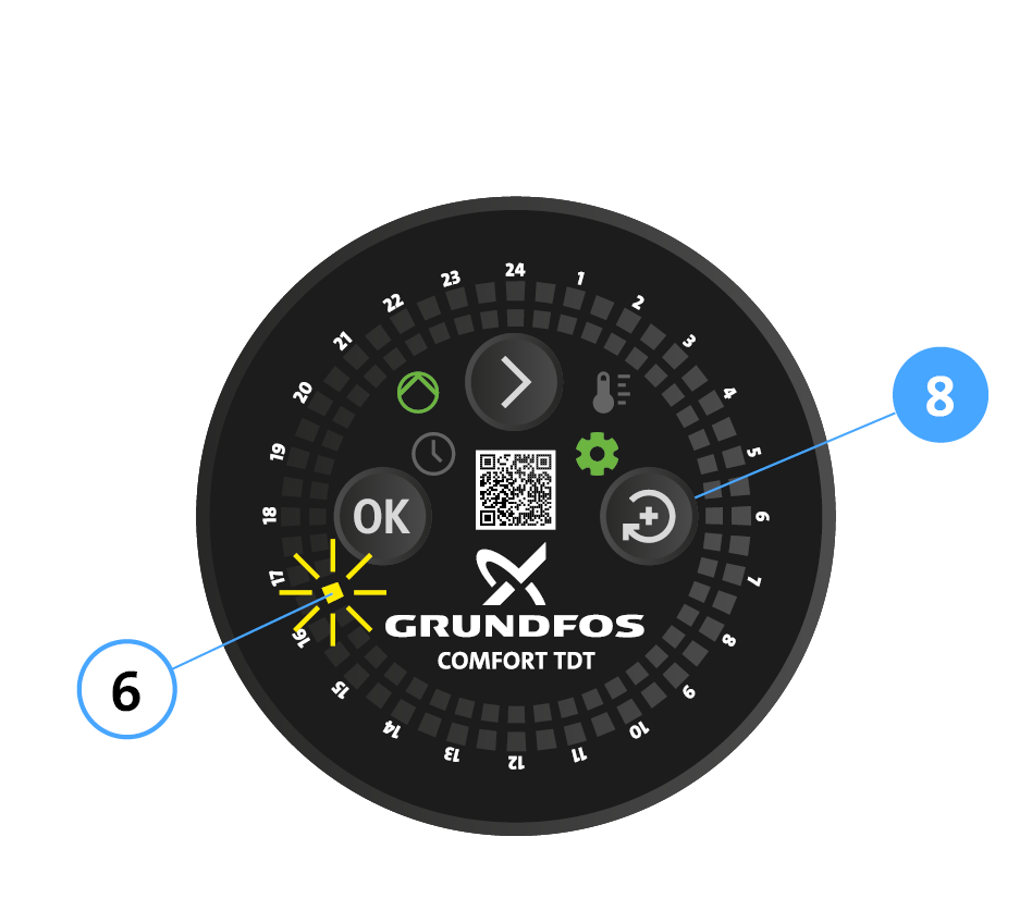
Press the Change button (8) repeatedly until the time LED reaches the current time (4:30 PM in this example). Note: The LED moves more quickly if the setting button (8) is held down.
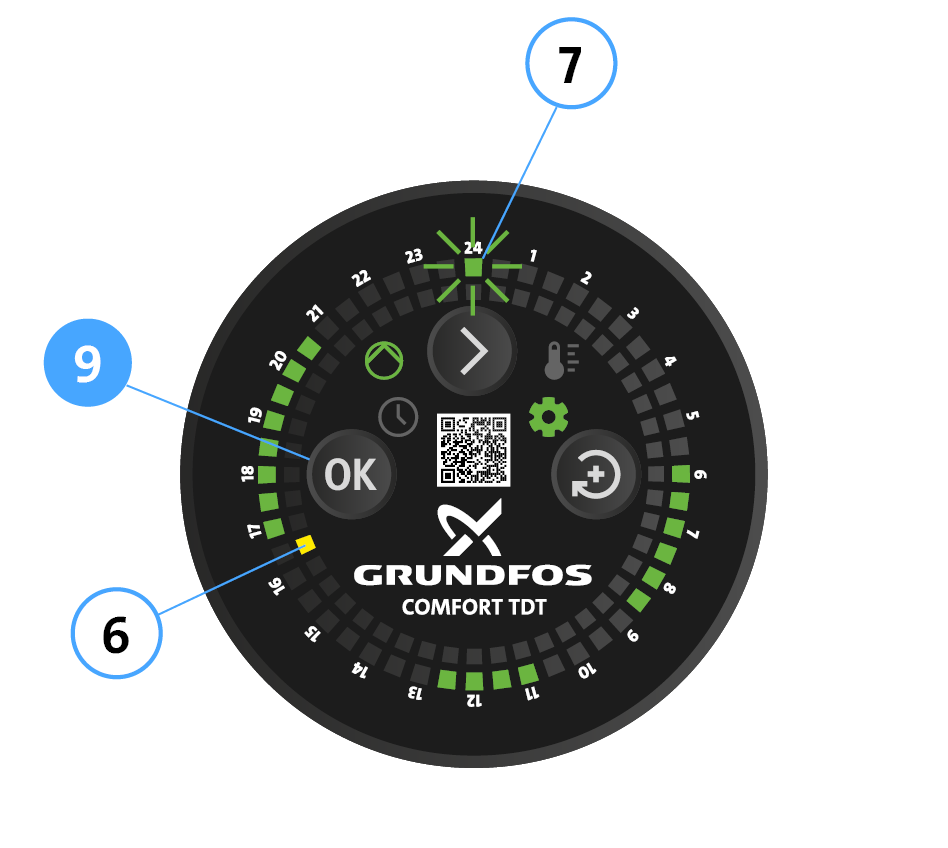
Press OK (9) to confirm. The time LED (6) now has a steady yellow light. The actual time has been set. The operating time LED (7) 0:00 – 0:30 AM has a flashing green light and already selected operating times are indicated.
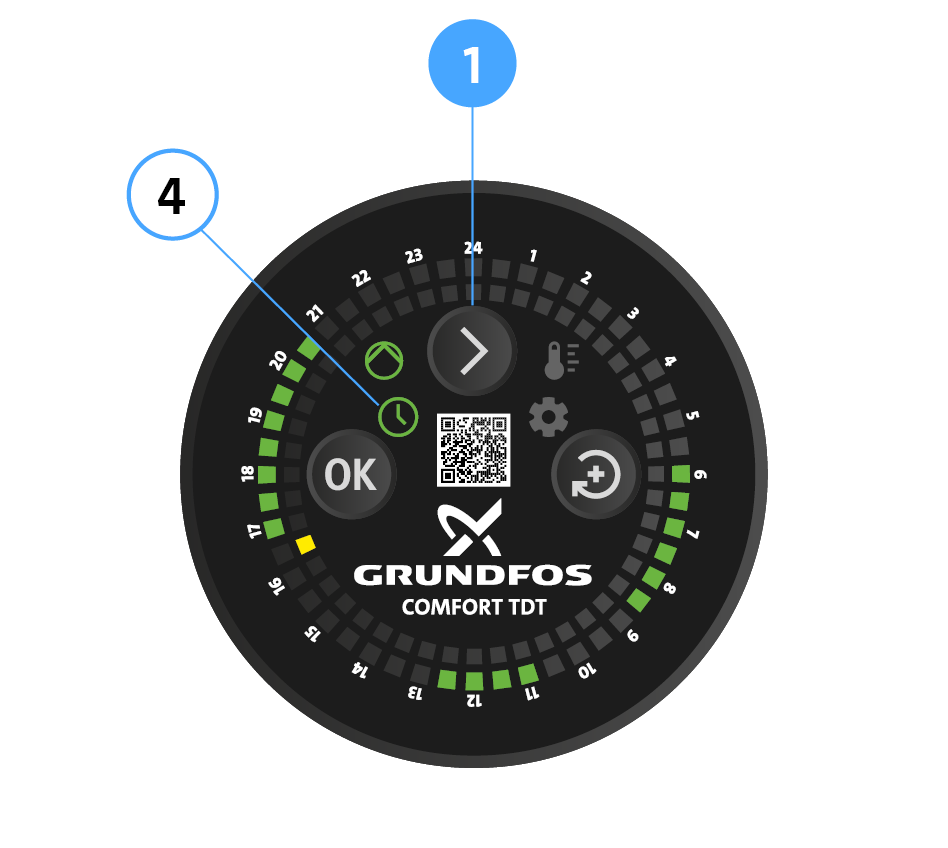
Press Arrow button (1) to exit setting mode. Timer mode LED (4) lights up. The actual time and already selected operating times are indicated.


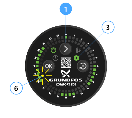
- Press Arrow button (1) repeatedly until the setting mode LED (3) has a steady green light. The actual time LED (6) has a flashing yellow light.
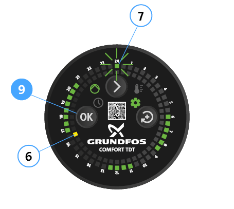
Confirm the time with OK (9). The actual time LED (6) has a steady yellow light. The operating time LED (7) 0:00 – 0:30 AM has a flashing green light.
Adding or deleting operating times
- Press the Change button (8) repeatedly until the flashing operating time LED is on the first required time segment (7) (e.g. 8:30 – 9:00 AM).
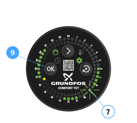
- To activate the time segment or delete an already activated time segment, press OK (9).
- The LED now has a steady green light or is off and the next time segment has a flashing green light (7).
- Activate this and subsequent time segments in the same way.
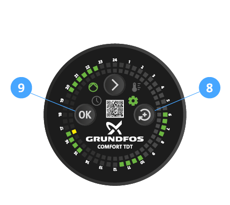
- To skip time segments, press the Change button (8) repeatedly. Then press OK (9) to activate or delete other time segments.
Example of a setting
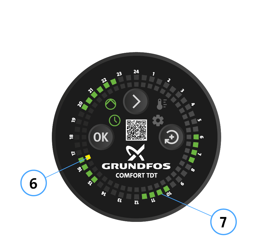
- The actual time LED (6) is between 4:00 and 4:30 PM.
- Operating times (7):
- 06:00 – 08:00 AM
- 10:00 AM – 12:00 PM
- 03:00 – 05:00 PM
- 08:00 – 11:00 PM
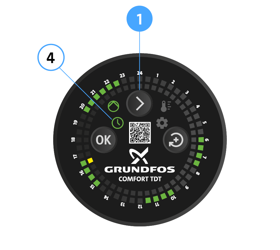
- When you have set all times, press the Arrow button (1) to exit setting mode. Timer mode LED (4) lights up. The selected operating times are indicated.


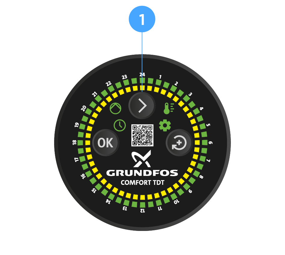
- Press Arrow button (1) for 5 seconds. All LEDs lights up for 1 second.
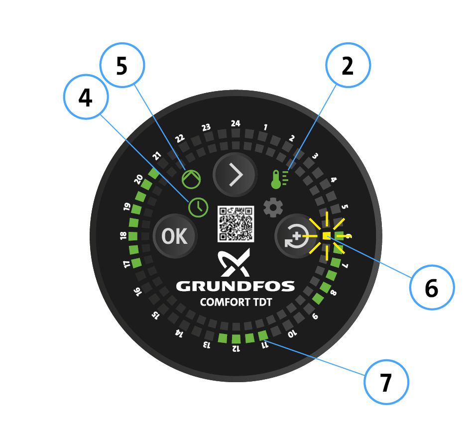
The pump returns to the factory settings:
- LED (4) Timer mode and LED (3) Temperature mode has steady green light.
- Pump operation LED (5) has steady green light.
- The yellow actual time LED (6) flashes at 06:00 AM (time segment 6:00 – 6:30 AM)
- Selected operating times (7) are following: - 06:00 – 09:00 AM
- 11:00 AM – 01:00 PM
- 05:00 – 09:00 PM
DANGER! Electric shock can kill!
- Before working on the pump, disconnect from the power supply and secure against reconnection.
- Check that no voltage is present.
DANGER! Pressurised system!
- Before working on the motor or pump connections, close the shut-off valves.
WARNING! Risk of scalding due to hot water!
- Avoid direct contact with escaping hot water.
- The pump housing can similarly reach a high temperature due to the hot medium being pumped.
- Whenever the motor is opened up, replace the seal in the pump housing.
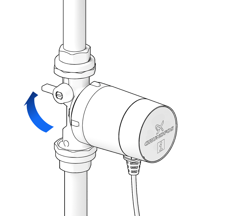
For maintenance, first close the shut-off valves.
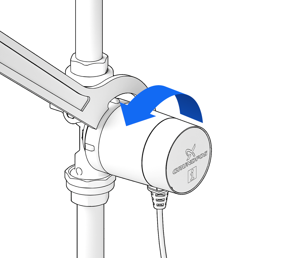
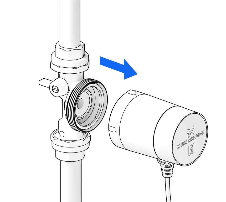
Unscrew the motor from the pump housing …
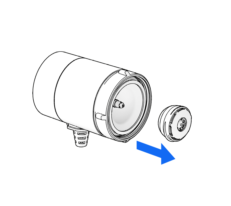
… Carefully lift the rotor off the bearing pin.
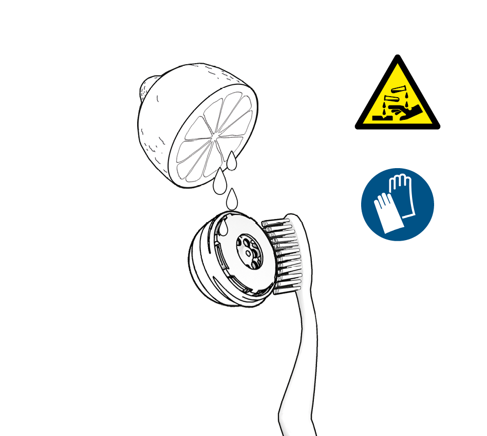
Using a limescale remover, free the rotor and separating cap of limescale. Use only soft, non-metallic tools (e.g. brush, cloth, toothpick).
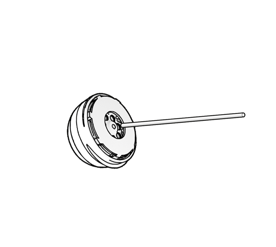
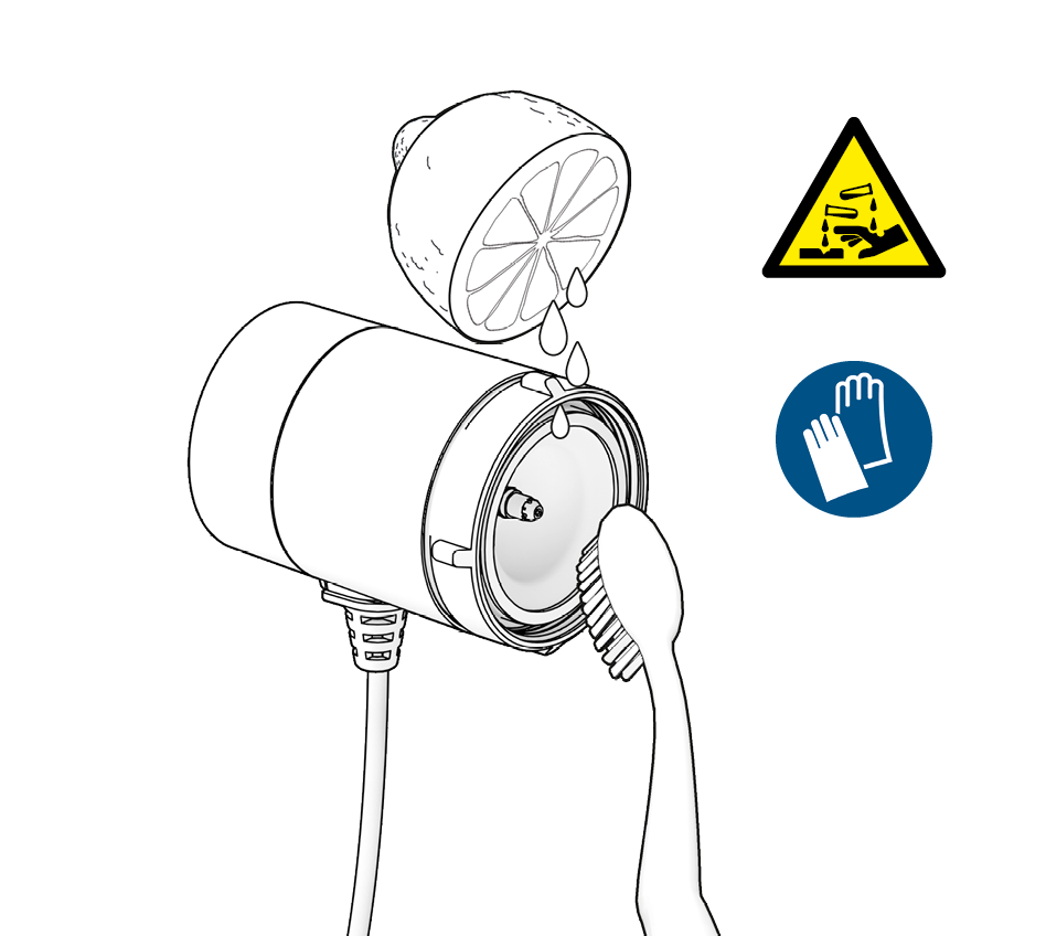
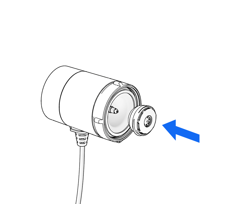
Reposition the rotor on the bearing pin.
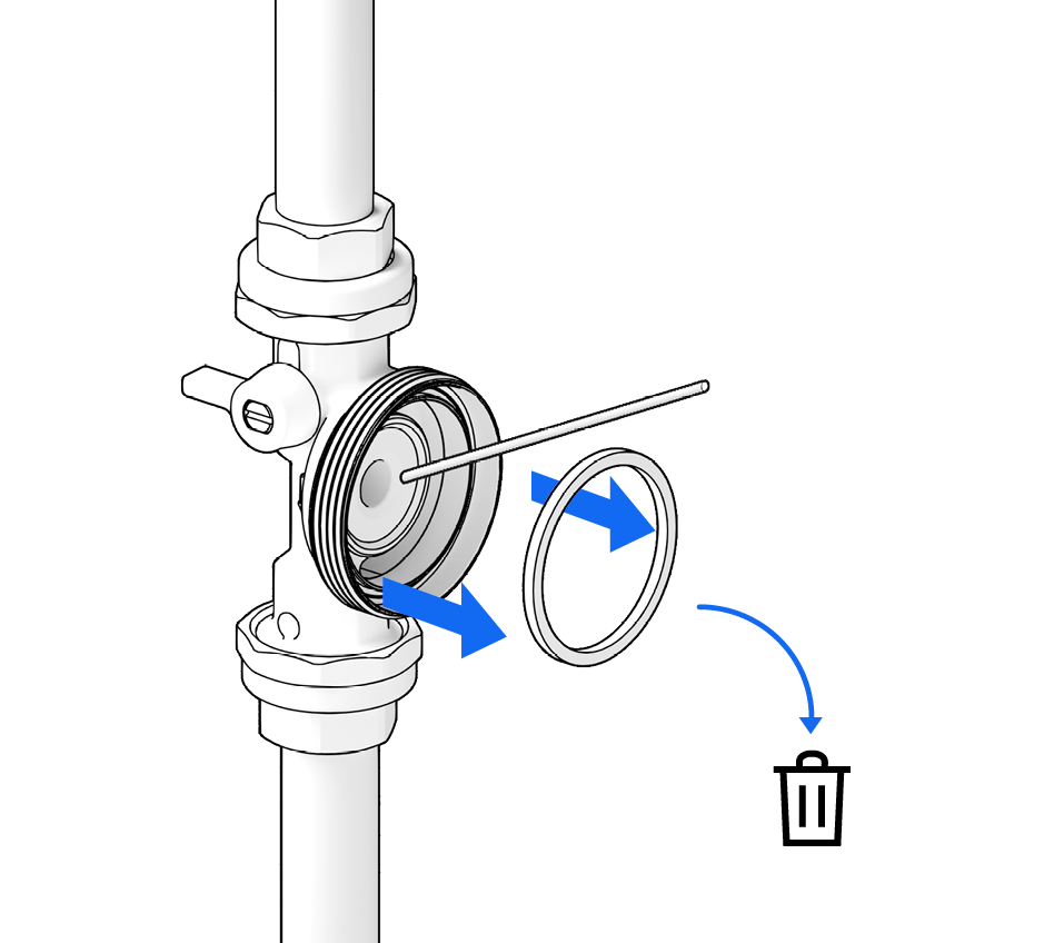
Remove the old seal.
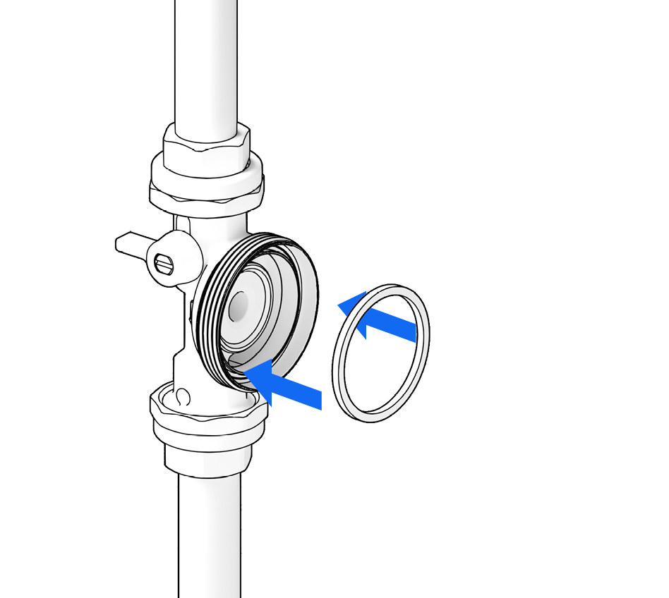
Insert new seal into the pump housing
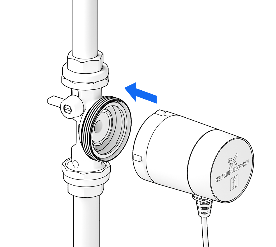
… and reattach the motor to the pump housing.
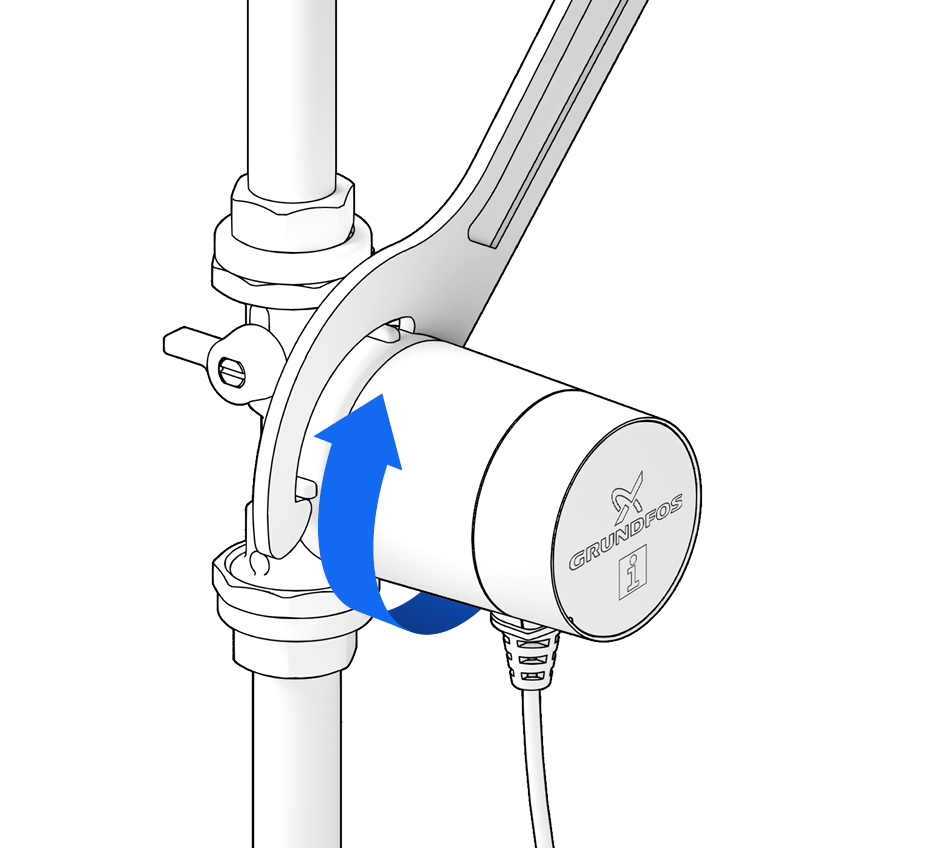
Retighten the union nut
(max. 20 Nm).
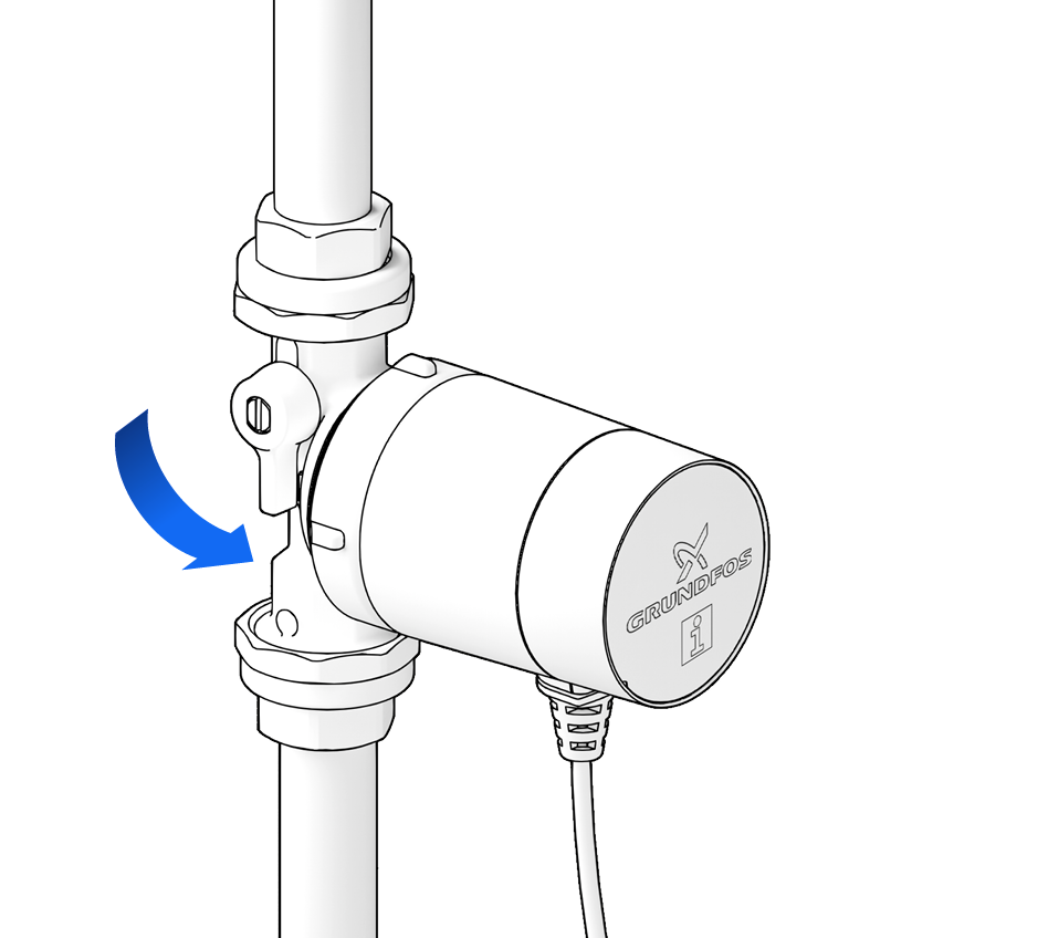
Slowly open the shut-off valves again.
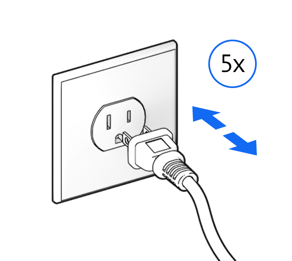
To vent any remaining air, switch the pump on and off several times …
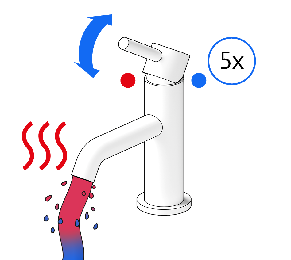
… and open the DHW tap several times …
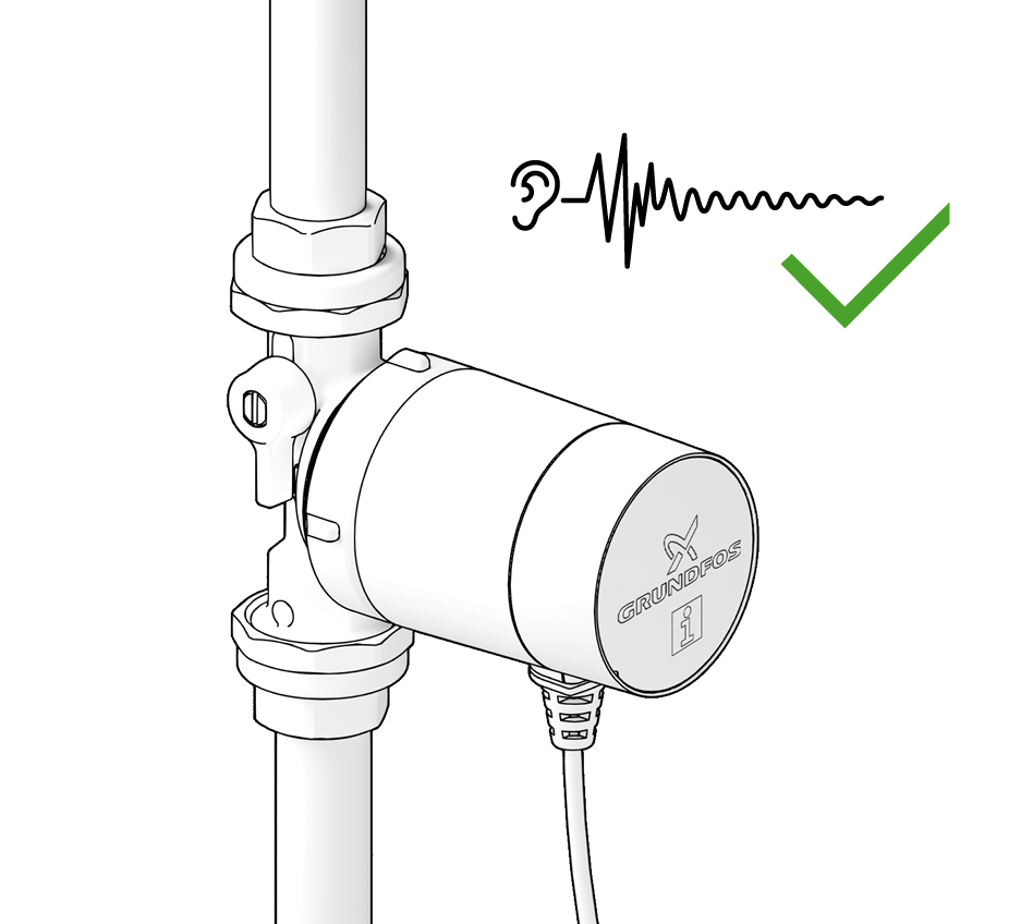
… until the pump runs quietly.
This Limited Warranty is provided for Consumer Products sold in the United States only and applies to Consumer Transactions as defined in and applicable under the Magnusson-Moss Warranty Act and any other applicable Federal and/or State laws. In case of non-Consumer Products, please refer to Grundfos’ warranty terms defined in clause 10 of Grundfos US Terms and Conditions of Sale of Product and Services available at https://www.grundfos.com/legal/grundfos-customer-terms/usa-grundfos-general-terms-for-sales-of-products-and-services
This Limited Warranty gives you specific legal rights, and you may also have other rights which vary from State to State.
New products manufactured by Grundfos are warranted to the original purchaser only and are to be free from defects in design, material and workmanship under normal use and service for no greater than a period of thirty (30) months from the date of manufacture which is set forth on the product’s nameplate and on the product’s packaging or the minimum period required by the applicable State law. For New Jersey, the applicable period is one year from the date of purchase.
The warranty period for replacement products, parts and components expires thirty (30) months from the original date of manufacture of the product originally purchased, unless a longer period is required under the applicable State law. For New Jersey, the warranty period for replacement products, parts and components expires one year from the original date of purchase of the product, not the date of replacement.
Products sold by Grundfos that are manufactured by others are not covered by this warranty.
Note that when purchasing a Grundfos product online, it is important to check the date of manufacture and the duration of the warranty with the seller as the product might no longer be covered under this Limited Warranty.
When a product is subject to this Limited Warranty a purchaser should contact the seller from which it purchased the product to make a claim.
If the seller of a product is no longer in business, the purchaser should complete the Grundfos Service form here: Contact Service.
As part of making a claim, a purchaser shall return a defective product at the purchaser’s cost, to the extent allowed by applicable law, along with proof of purchase and an explanation of the defect, date the defect occurred and circumstances surrounding the defect. For New Jersey there is no prohibition on returning a defective product at a purchaser’s cost. If Grundfos is required by applicable State law to pay for the cost of shipment under applicable State law, then a purchaser should contact a Grundfos Authorized Service Partner to arrange for shipment. A purchaser also needs to promptly respond to Grundfos as to any inquiries regarding a warranty claim.
Grundfos’ liability under this Limited Warranty to purchaser is limited to the repair or replacement of a product (at Grundfos’ decision) that is the sole and exclusive remedy for purchaser to the extent permissible by applicable law. For New Jersey this limitation is permissible.
This warranty does not cover the following: ordinary wear and tear; use of a product for applications for which it is not intended; use of a product in an unsuitable environment; modifications, alterations or repair undertaken by anyone not acting with Grundfos’ written authorization; failure to follow Grundfos’ instructions, operations manuals, any other guidelines or good industry practice; use of faulty or inadequate ancillary equipment in combination with a product; application of spare or replacement parts not provided or authorized by Grundfos; accidental or intentional damage or misuse of a product.
The time period for making a claim under the implied warranty of merchantability and implied warranty of fitness are limited to the same time period as provided by this warranty to the extent permissible by applicable law. For residents of New Jersey, this limitation is permissible, but note that some states do not allow limitations on how long an implied warranty lasts, so the above limitation may not apply to you.
Grundfos shall not be liable for any incidental and consequential damages in connection with a product to the extent permissible by applicable law. For residents of New Jersey, this limitation is permissible, but note that some states do not allow limitations of incidental or consequential damages, so the above limitation may not apply to you.
The correct disposal of packaging in separate collection is
fundamental for optimization of the recycling processes. The packaging
materials should be correctly disposed of in separate collection, sorted
and recycled according to the provisions of your local authority. The
symbols included on the packaging material will help you to identify the
material category to perform the correct separation.
See what packaging materials Grundfos products use and how to correctly dispose of them by clicking on this link:
U.S.A.
Global Headquarters for WU
856 Koomey Road
Brookshire, Texas 77423 USA
Phone: +1-630-236-5500
GRUNDFOS CBS Inc.
902 Koomey Road
Brookshire, TX 77423 USA
Phone: 281-994-2700
Toll Free: 1-800-955-5847
Fax: 1-800-945-4777
GRUNDFOS Pumps Corporation
9300 Loiret Boulevard
Lenexa, Kansas 66219 USA
Phone: +1 913 227 3400
Fax: +1 913 227 3500
Canada
GRUNDFOS Canada inc.
2941 Brighton Road
Oakville, Ontario
L6H 6C9
Phone: +1-905 829 9533
Fax: +1-905 829 9512
Mexico
Bombas GRUNDFOS de México
S.A. de C.V.
Boulevard TLC No. 15
Parque industrial Stiva Aeropuerto
Apodaca, N.L. 66600
Phone: +52-81-8144 4000
Fax: +52-81-8144 4010